
 English
Views: 0 Author: Site Editor Publish Time: 2026-09-18 Origin: Site


Selecting the wrong structural specifications in industrial construction leads directly to operational bottlenecks, delayed timelines, and severe project overruns. Facility managers and developers face a complex reality on the ground. You have to align heavy machinery requirements, workflow logistics, and climate control needs with strict local zoning laws. Structural load demands and site-specific constraints complicate the site planning phase even further. Navigating these overlapping requirements demands a systematic evaluation framework rather than guesswork. This guide provides actionable steps to specify an Industrial Steel Building that meets your current operational demands. We break down exactly how to evaluate spatial needs, foundation engineering, and local codes. By following this framework, you ensure the facility maintains structural flexibility for future scalability while avoiding the common pitfalls that derail industrial construction projects.
Defining exact spatial requirements (clear-span vs. multi-span) is the critical first step in determining the structural framework of an industrial steel building.
Local building codes—specifically wind, snow, and seismic load requirements—dictate the engineering specifications and baseline costs.
Foundation preparation and accurate anchor bolt placement are the most common failure points in steel building erection; mitigating these requires specialized geotechnical and engineering oversight.
Calculating the required square footage goes far beyond measuring the perimeter. You must map out the exact footprint of manufacturing lines, warehousing racks, and staging areas. Factor in aisle widths based on specific material handling equipment. A standard sit-down counterbalanced forklift requires significantly wider aisles than a narrow-aisle reach truck or a wire-guided turret truck. Vertical clearance demands equal attention. Facility owners often confuse eave height with clear height. Eave height measures the distance from the finished floor to the intersection of the sidewall and the roof. Clear height represents the actual usable space below the lowest hanging structural member, such as a rafter haunch. If your operations require twenty feet of vertical space to stack pallets safely, a twenty-foot eave height will fail. The rafter haunches typically drop two to three feet at the column connections, reducing your usable space. Overhead door clearance also dictates minimum wall heights. A fourteen-foot tall overhead door requires at least a sixteen-foot eave height to accommodate the door track, drum, and motorized operator. Integrating mezzanine floors for administrative offices above the manufacturing floor requires heavier columns and specialized floor joists to handle the increased live loads.
The choice between clear-span and multi-span framing dictates the fundamental engineering of the entire structure. Clear-span architecture provides completely unobstructed floor space. The structural frame spans from one sidewall to the other without any interior support columns. This design utilizes massive, tapered columns and deep rafter beams to carry the roof load across the entire width. Clear-span designs are mandatory for large-scale manufacturing facilities, aircraft hangars, and heavy equipment maintenance shops where interior columns would disrupt workflow or cause equipment collisions. Multi-span frames, often called modular frames, use interior columns to support the roof structure. This configuration significantly reduces the size, weight, and cost of the primary framing members. Multi-span designs suit massive distribution centers and logistics warehouses where minor floor obstructions remain acceptable. Racking systems can easily incorporate interior columns into their layout without losing pallet positions.
| Feature | Clear-Span Configuration | Multi-Span Configuration |
|---|---|---|
| Interior Space | 100% unobstructed floor area | Interrupted by support columns |
| Maximum Width | Typically up to 300 feet | Virtually unlimited with columns |
| Primary Framing | Massive, heavy tapered columns | Lighter, straight or tapered columns |
| Foundation Impact | Requires massive concrete footings | Distributes weight, smaller footings |
| Best Application | Hangars, heavy manufacturing | Distribution centers, large warehouses |
Adding overhead bridge cranes heavily impacts the structural design of the facility. Jib cranes, heavy rooftop HVAC units, and suspended conveyor systems introduce significant dynamic and static loads. You must communicate these collateral load requirements to the structural engineer during the initial design phase. The engineering team will reinforce the framework to support these loads safely. Top-running bridge cranes require dedicated runway beams supported by structural brackets welded directly to the main building columns. The building frame must resist the lateral and longitudinal forces generated when a fully loaded crane starts, stops, or travels down the runway. Heavy rooftop HVAC units require reinforced roof purlins and specialized roof curbs to distribute the weight evenly and prevent water intrusion. Standard collateral loads for lighting and fire sprinklers usually run between three and five pounds per square foot (psf). Failure to account for heavy equipment loads leads to structural deflection. Deflection causes roof leaks, misaligned overhead doors, and potential structural failure under maximum capacity.
Utilizing manufacturer-provided 3D Building Information Modeling (BIM) software during the conceptual phase eliminates guesswork. These tools allow project managers to accurately model dimensions, structural shapes, and spatial flow before any steel is cut. Visualizing door placements and window alignments prevents layout conflicts on the job site. You can verify that overhead doors do not interfere with interior crane runways or mezzanine staircases. 3D modeling facilitates clash detection between primary structural members and mechanical systems. Engineers can route HVAC ductwork, fire sprinkler mains, and electrical conduit virtually. This digital coordination prevents change orders during the fabrication or erection phase. Change orders in the field cause severe project delays and require expensive field-welding or structural modifications. Visualizing exterior color combinations in a 3D environment also ensures compliance with corporate branding guidelines and helps secure rapid approval from local architectural review boards.
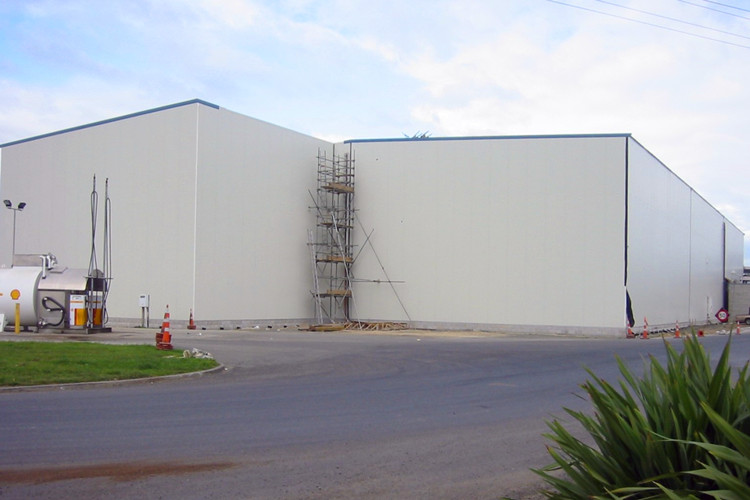
Site selection depends heavily on proximity to transit routes, soil stability, and natural drainage patterns. Natural topography dictates the site grading requirements and earthwork volume. Poor site grading compromises the foundation directly. You must direct surface water away from the concrete slab using a minimum slope of five percent for the first ten feet. Inadequate water runoff planning leads to soil erosion beneath the footings. Erosion causes structural settling over time. Settling misaligns the rigid steel frame, causing overhead doors to jam, roof panels to tear at the fasteners, and wall panels to buckle. Evaluate the site for heavy truck accessibility early in the planning phase. Fifty-three-foot flatbed trailers deliver the structural components. These trucks require wide turning radii, stable ground for unloading, and clear overhead access free of power lines. Soft or muddy sites require temporary gravel access roads and crane pads to prevent equipment from sinking during erection. Plan cut-and-fill operations carefully to create a level, highly compacted building pad.
A professional soil test determines the required concrete slab thickness, footing depth, and reinforcement requirements. Never skip the geotechnical survey. Soil bearing capacity varies drastically across different regions and even across a single large parcel of land. Expansive clay soils require entirely different foundation designs than stable sandy soils. The structural engineer uses the formal soil report to design the foundation plan, specifying the exact concrete compressive strength (psi) and rebar layout. Anchor bolt placement remains the most critical failure point during the entire erection process.
Conduct core drilling to determine the exact soil bearing capacity and identify any subsurface water tables.
Excavate and compact the building pad to a minimum of 95% Standard Proctor density.
Form the concrete footings and install hairpin rebar to resist the outward lateral thrust generated by the rigid frame columns.
Secure rigid anchor bolt templates to the wooden forms to ensure millimeter-level accuracy before the concrete pour.
Pour the concrete and allow adequate curing time before subjecting the foundation to the heavy point loads of the steel columns.
Installers cast anchor bolts directly into the concrete foundation. The steel columns feature pre-punched base plates fabricated to exact tolerances. If the anchor bolts do not align perfectly with these holes, the erection crew must halt work. Field-modifying base plates compromises the structural integrity and voids manufacturer warranties.
Verify zoning restrictions and setback requirements with local municipalities before finalizing any site plans. Setbacks dictate exactly how close the structure can sit to the property lines, easements, or existing structures. Some jurisdictions enforce strict aesthetic mandates in industrial parks. They may require specific exterior facades like brick veneer, stucco panels, or architectural glass on street-facing walls. Securing commercial building permits requires detailed architectural and engineering documentation. You must submit stamped structural drawings generated by an engineer licensed in that specific state. Local fire marshals dictate fire rating requirements and sprinkler system mandates based on the intended use of the facility. Occupancy classifications determine egress door locations, travel distances, and emergency lighting requirements. An F-1 moderate-hazard factory classification carries vastly different code requirements than an S-2 low-hazard storage classification. Navigating these codes requires seamless coordination between the structural engineer, the architect, and local building officials.
Local wind ratings, ground snow loads, and seismic zones dictate the structural design of the framing members. Engineers calculate these environmental load requirements to ensure the frame withstands extreme weather events without failure. Wind exposure categories matter significantly in the engineering software. An open terrain environment (Exposure C) increases wind pressure on the walls and roof compared to a suburban area surrounded by other buildings (Exposure B). High wind zones require heavier structural cable bracing, rigid portal frames, and closer purlin spacing to resist massive uplift forces. Heavy snow loads require steeper roof pitches or reinforced rafter beams to carry the static weight. Stepped roofs or adjacent taller buildings create areas for snow drift accumulation. Engineers must account for these localized heavy loads to prevent roof collapse. Never purchase off-the-shelf kits without verifying the engineering stamps. The engineering must match your specific county's current building codes. Installing an under-engineered structure risks catastrophic failure. Always provide the exact job site address to the manufacturer for accurate, site-specific load calculations.
Installing a high-performance insulation envelope dictates the long-term mechanical demands of the facility. Standard fiberglass blankets require a reinforced vapor barrier, typically a WMP-VR facing, to prevent interstitial condensation. Installers drape these blankets directly over the roof purlins before securing the exterior panels. This installation method compresses the fiberglass at the purlin lines, significantly reducing the effective R-value. To mitigate this thermal bridging, crews must install extruded polystyrene thermal blocks between the purlins and the roof panels. Insulated Metal Panels (IMPs) offer a premium alternative for climate-controlled environments. IMPs consist of a dense polyurethane foam core injected between two steel face panels. They provide superior thermal performance, install rapidly, and provide a finished interior wall surface simultaneously.
| Insulation Type | Installation Method | Thermal Performance | Best Application |
|---|---|---|---|
| Fiberglass Blankets | Draped over framing | Moderate (susceptible to compression) | Basic warehouses, dry storage |
| Rigid Board | Fitted between girts/purlins | High (consistent R-value) | Workshops, light manufacturing |
| Insulated Metal Panels | Attached directly to exterior | Superior (eliminates thermal bridging) | Cold storage, food processing |
Standard PBR (Purlin Bearing Rib) steel panels offer functional, durable coverage for exterior walls. These 26-gauge or 24-gauge panels overlap and fasten directly to the wall girts. Architectural panels meet strict aesthetic codes or corporate branding needs. They feature hidden fasteners and flat profiles for a modern, streamlined appearance. For roofing, standing seam metal roofs (SSR) heavily outperform standard screw-down roofs. Screw-down roofs utilize thousands of exposed fasteners with rubber washers. Each fastener represents a potential leak point as the rubber degrades under UV exposure over time. Standing seam systems conceal the fasteners entirely beneath the panel ribs. A mechanical seamer folds the panel edges together, creating a highly weather-tight seal. Standing seam roofs utilize sliding clips that attach to the purlins. These clips allow the entire roof plane to expand and contract freely with daily temperature changes, preventing fastener back-out. High-quality trim packages and flashing ensure long-term weatherproofing. Base trim, eave trim, and rake trim provide a professional finish and seal vulnerable joints against wind-driven rain.
Industrial operations generate heat, moisture, and exhaust fumes that require active management. Integrate continuous ridge vents and wall louvers to facilitate natural cross-ventilation. Exhaust fans help manage internal temperatures during summer months and maintain required air changes per hour (ACH). Gravity ventilators allow hot air to escape through the roof peak naturally without consuming electricity. Proper ventilation prevents condensation buildup inside the structure, which can drip onto machinery or inventory. Strategic placement of skylights and wall lights reduces electrical lighting loads during daytime shifts. Translucent polycarbonate panels allow natural daylight to enter the workspace while resisting impact damage. Properly engineered lighting integration maintains the structural integrity of the roof and wall panels. Installers must seal skylights meticulously with mastic tape and specialized flashing to prevent water intrusion. Coordinate ventilation and lighting requirements during the initial design phase. Retrofitting these elements later requires cutting into the finished panels, which compromises the weather-tight envelope.
Evaluate material specifications carefully before finalizing a design. Selecting lower-tier options often compromises steel gauge thickness and long-term performance. Thinner steel panels dent easily from minor impacts and provide less structural rigidity against wind loads. Paint warranties vary significantly between manufacturers and directly impact the lifespan of the exterior. A standard SMP (Silicone Modified Polyester) paint system chalks and fades much faster than a premium PVDF (Polyvinylidene Fluoride) coating. PVDF coatings resist UV degradation, chemical exposure, and industrial fallout effectively, keeping the facility looking new for decades. Commercial-grade steel provides unmatched long-term durability regarding pest resistance. Termites, carpenter ants, and rodents cannot damage or nest within solid steel framing. Steel also offers superior fire safety compared to traditional wood framing, as it is non-combustible. A robust Steel Building resists structural degradation over decades of heavy industrial use, maintaining its structural integrity in harsh environments.
Pre-engineered structures erect significantly faster than traditional masonry or conventional steel construction methods. The manufacturer cuts, welds, drills, and paints all primary framing members at the factory under strict quality control standards. However, faster on-site assembly requires rigorous upfront planning. Detailing and fabrication take several months before any materials arrive on site. Project managers use the critical path method to manage these overlapping timelines, ensuring the foundation cures exactly as the steel arrives. The final stages of erection demand meticulous attention to detail. Primary framing goes up quickly using cranes and boom lifts, but final trim work requires precision hand tools. Crews must tighten structural bolts using the turn-of-nut method to achieve the exact required tension. Sealing and weatherproofing are just as critical as the primary structural framing. Rushing the trim installation leads to roof leaks, drafty wall panels, and pest intrusion. Allocate sufficient time in the construction schedule for detailed finishing work and final inspections.
Miscommunication between the steel manufacturer, the concrete contractor, and the erection crew creates severe delays and expensive rework. The erection crew relies entirely on accurate foundation dimensions and perfectly placed anchor bolts. Acting as an owner-builder carries high risk if you lack commercial construction management experience. You must coordinate multiple specialized trades simultaneously, manage equipment rentals, and schedule municipal inspections. Hire a single-source design-build contractor or a dedicated project manager. This ensures accountability across all phases from foundation excavation to final trim installation. The project manager handles the Request for Information (RFI) process, clarifying engineering details with the manufacturer. They review submittals, coordinate delivery schedules, and enforce site safety protocols. Clear communication channels prevent costly rework. Establish a regular meeting schedule with all key contractors before breaking ground to align expectations and review the critical path schedule.
Receiving multiple flatbed deliveries of heavy steel components presents immediate logistical challenges on a busy job site. Stage materials systematically to prevent damage, loss, and erection delays.
Designate a flat, dry, and highly compacted staging area before the delivery trucks arrive.
Unload heavy structural frames separately from delicate exterior panels and trim pieces.
Place heavy columns and rafters on wooden dunnage to keep them out of the mud and prevent surface rust.
Cross-reference the bill of materials immediately upon delivery to identify any shipping shortages.
Report any missing or damaged components to the manufacturer immediately to expedite replacements.
Protect insulation rolls and specialized fasteners from weather exposure using heavy-duty tarps.
Wet fiberglass insulation loses its thermal resistance permanently and promotes mold growth inside the wall cavity. Store fasteners, mastic tape, and small hardware in a secure, dry shipping container to prevent loss or theft. Proper material staging accelerates the shake-out process, allowing the erection crew to locate specific pieces instantly without moving heavy steel multiple times.
Choosing the right industrial structure requires balancing immediate operational needs with strict structural engineering realities. You must plan for long-term scalability while adhering to complex local building codes and environmental load requirements. Select a manufacturer or contractor based on verifiable engineering credentials and a proven track record in your specific industry. Demand transparent load calculations and the utilization of 3D BIM design tools to prevent field conflicts.
Take the following actions to initiate your facility planning phase:
Hire a geotechnical firm to perform core drilling and issue a formal soil report for your specific lot.
Map out your exact equipment footprint, including forklift turning radii and maximum crane lifting capacities.
Submit a preliminary site plan to the local zoning board to verify setback requirements and aesthetic mandates.
Request structural design proposals from manufacturers that utilize 3D BIM software for clash detection.
A: Final pricing fluctuates based on clear-span width, eave height, and environmental load requirements. High wind zones or heavy snow loads require thicker steel and closer frame spacing, increasing material volume. Premium additions like standing seam roofs, insulated metal panels, and heavy crane runway beams also drive up the baseline square footage rate.
A: Pre-engineered structures utilize standardized, highly efficient structural software to optimize material use and fabrication speed. Manufacturers produce these frames using established engineering templates. Custom designs are required for highly irregular shapes, extreme heavy-industrial loads, or unique architectural integration that falls outside standard parameters.
A: The timeline breaks down into design and engineering, fabrication, site preparation, primary erection, and final trim phases. While the physical on-site erection is rapid, upfront engineering and factory fabrication often take several months. Proper site preparation occurs concurrently with fabrication.
A: Structural engineers handle the primary frame design and load calculations. However, an architect may be required by local municipalities. Architects ensure exterior aesthetic compliance, life-safety code adherence, and design complex interior office build-outs within the industrial shell.
A: Yes. Expandable end-walls can be engineered into the initial design phase. This structural feature allows for future modular additions. You can extend the length of the facility later without compromising the original structural integrity or requiring massive retrofits.
A: Common options include monolithic slabs and pier and curtain wall systems. The exact foundation type depends entirely on site-specific geotechnical engineering. Soil bearing capacity, frost lines, and the total weight of the structural frame dictate the final foundation design.
